Procurement Resource / Configuration Decision
Light Box Sidedness & Mounting Guide
Compare single- and double-sided viewing with wall, suspended, freestanding and project-specific placement before the frame, structure and supply scope are reviewed.
Single-sided usually starts from one primary viewing direction. Double-sided starts from two viewing directions. The final structure, depth, lighting, mounting and supplied condition remain project-specific.
01 / Sidedness
Choose the viewing requirement before the profile
Sidedness is a project input, not a universal promise about one profile or mounting method.
One main viewing direction or a rear surface that is not used for graphics.
Two active viewing directions; describe traffic, sight lines and whether both faces require illumination.
Often discussed for a wall or another one-direction application.
Often discussed for suspended, projecting or freestanding visibility.
Viewing direction, rear interface, access and graphic-change requirement.
Both sight lines, overall geometry, base/rigging context and access to each face.
Exact section, lighting space, rear condition, mounting and supply state.
Exact section, internal structure, lighting arrangement, balance, mounting/base and supply state.
02 / Mounting & placement
Four placement paths, each with different questions
Wall-mounted
Provide wall/substrate context, overall size, access, rear interface and responsibility for local fixing or installation.
Suspended
Provide suspension points, height, sidedness, viewing direction and who will confirm rigging, loads and local installation.
Freestanding
Provide footprint, base direction, circulation, sidedness, access and whether the display will be moved or remain in one location.
Project-specific interface
Use an authorized drawing or reference to explain a projecting, recessed, integrated or non-standard condition.
03 / Real project context
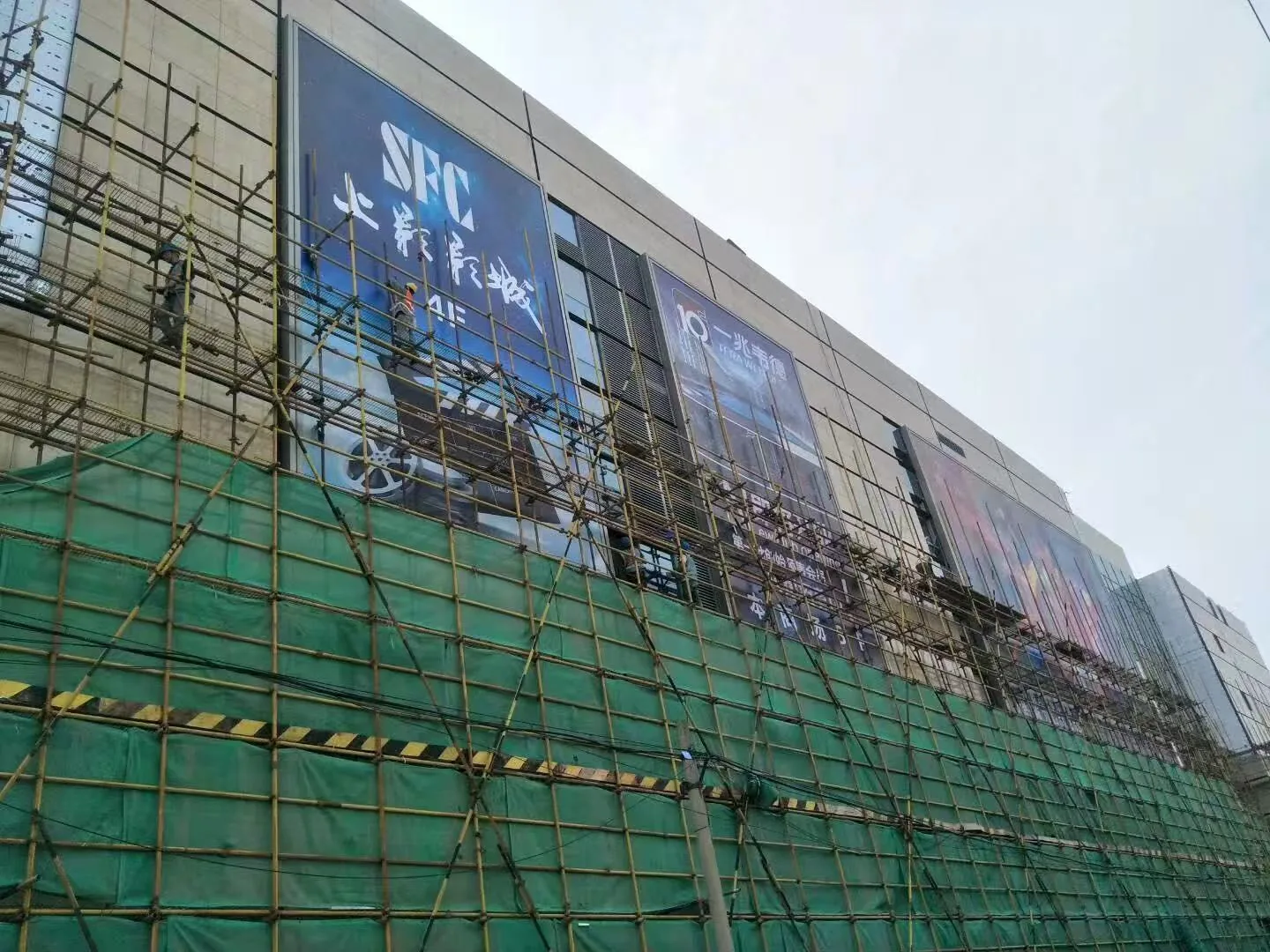
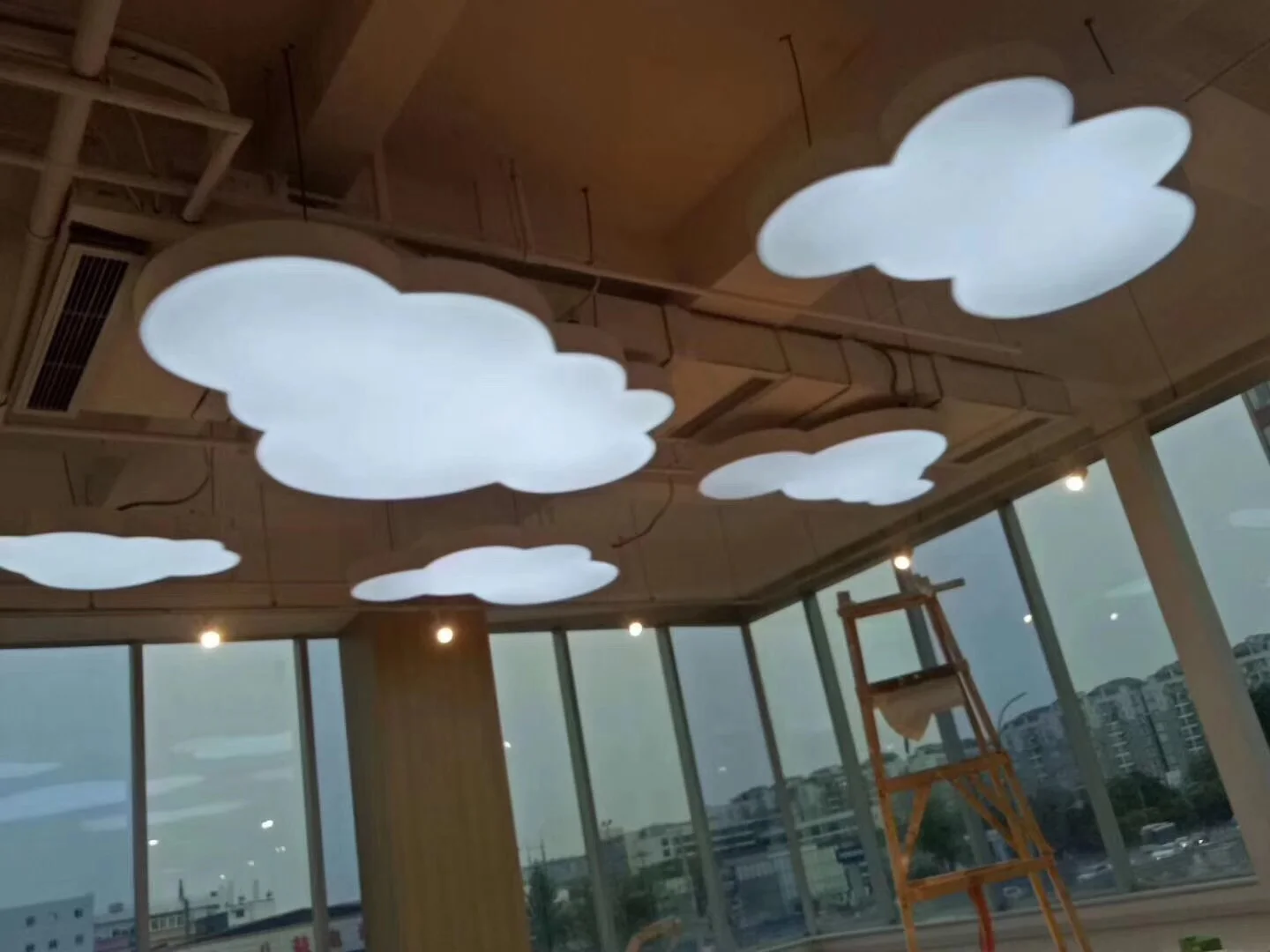
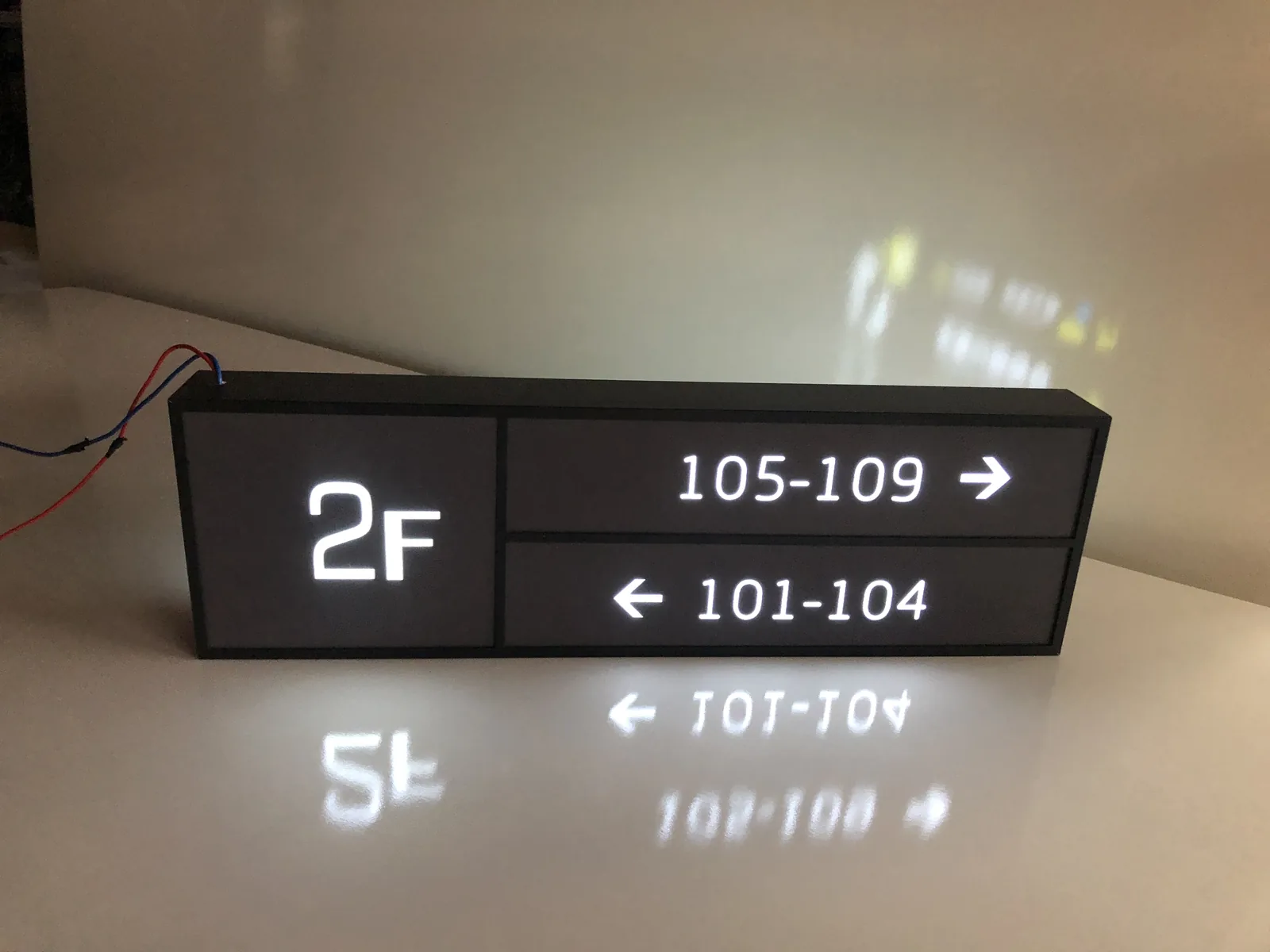
Placement decisions change with scale, form and use
These approved examples show different project contexts. They do not establish universal mounting, load or installation rules.
04 / Responsibility boundary
This guide selects questions, not anchors or engineering values
The project brief should identify who is responsible for local measurement, substrate verification, structural or rigging review, power, permits and installation.
Confirm locally
Wall composition, ceiling/rigging structure and supporting surfaces are not inferred from an application label.
Not specified here
This guide does not publish anchor type, load capacity, span, wind or structural values.
Describe the context
State available power, service access and responsibility; exact electrical scope remains project-specific.
Separate scope
Available supply and local installation responsibilities are confirmed for the actual project.
05 / Buyer preparation
What to send for sidedness and mounting review
Application & viewing
Location, audience, sight lines and whether one or two faces are active.
Overall geometry
Width, height, quantity, orientation and any non-standard outline.
Placement context
Wall, suspended, freestanding or project-specific interface.
Site information
Known substrate, access, rigging/base context and local responsibility.
Graphic & lighting
Graphic change expectation, illumination intent, destination and control requirement.
Commercial brief
Quantity, destination, target date and intended supply state.
Review the actual placement
Bring the viewing direction, geometry and site context.
The profile, sidedness, mounting, supply scope and commercial conditions are confirmed only after human review of the project.