Project Example / Physical Sample Development
Custom-Shaped Illuminated Structure Development
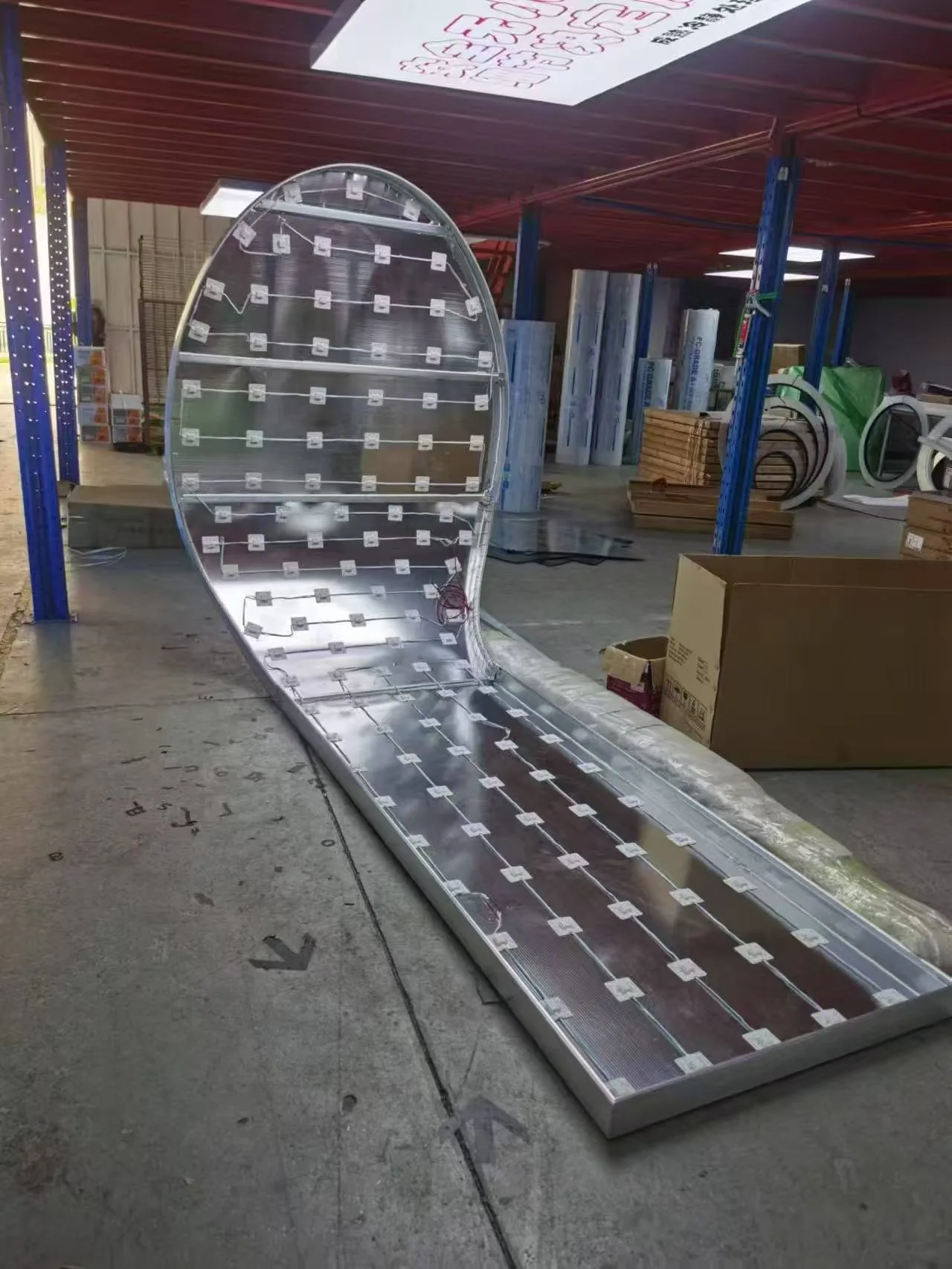
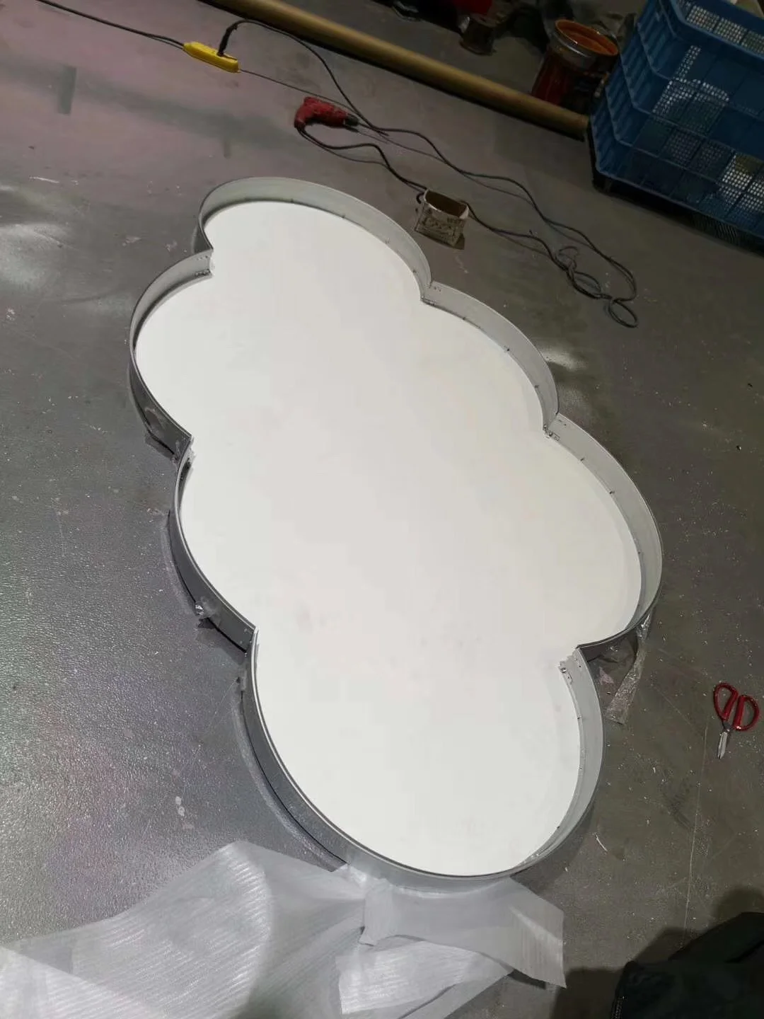
Ningora developed and fabricated a non-rectangular illuminated form from a dimensioned concept through shaped rear structure, distributed lighting nodes, module checks and workshop light-on review.
Why the requirement was unusual
The outline, module breaks and lighting pattern had to work together
A custom outline cannot be reviewed as a standard rectangular frame. The drawing, rear structure, handling strategy and light-on result become connected decisions.
Dimensioned concept
A drawing established the intended non-standard outline and the starting geometry.
Shaped rear structure
The physical rear assembly follows the irregular form and carries distributed lighting nodes.
Module review
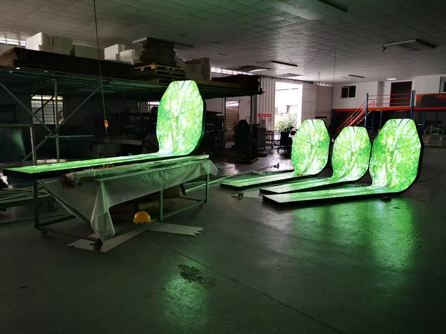
Several illuminated modules were checked on workshop tables before upright assembly.
Fabrication-stage result
The visible sequence records physical development, not a completed customer installation.
Development-stage views
Structure first, then light-on review
The rear view shows how the non-standard outline was translated into a lightable structure; the workshop view shows multiple modules during function checks.
What to send for a similar form
Make the shape reviewable before asking for a quotation
Authorized outline
Vector or dimensioned drawing showing the intended perimeter and important openings.
Overall dimensions
Width, height, unit, quantity and any panel or module limits.
Viewing and mounting
Front/back visibility, suspension or wall context, access and handling constraints.
Lighting intent
Static or controlled lighting requirement, destination voltage and expected visual effect.
Surface and finish
Face material, colour direction and any physical sample that should guide review.
Target stage
Prototype, fabrication-stage sample or another defined deliverable for confirmation.
Project takeaway
Custom shape becomes credible when the physical development sequence is visible.
The useful question is not whether an outline is unusual, but whether the drawing, structure, lighting and handling constraints can be reviewed together.