Factory-Direct / Large-Format SEG Manufacturing
Large-Format SEG Light Boxes
Ningora manufactures large-format SEG and backlit fabric light box systems to confirmed project drawings for sign companies, large-format printers and display contractors. Frame geometry, sectioning, lighting, mounting interface, supplied condition and packing are defined for the actual project.
01 / Product Definition
Large format changes the configuration, not just the dimensions
A large-format SEG light box connects the finished display geometry with frame divisions, fabric handling, rear-lighting layout, transport constraints, site access and the required supplied condition. Ningora confirms those decisions against the actual drawing instead of applying one profile or construction to every large display.
SEG/fabric graphic interface, aluminum frame, rear-lighting structure and project-specific site interface.
Commercial facades, wide-format branded displays and large illuminated fabric graphics.
Finished geometry, drawings, quantity, site/access context, graphics, lighting, destination and required supplied condition.
Frame divisions, profile direction, lighting layout, interfaces, packing, MOQ and lead time.
Large-Format Planning Decisions
Plan the manufactured system, transport sections and site interface together
Large dimensions affect subdivision, profiles, rear structure, illumination, graphic tension, transport size and local installation conditions. The Shanghai project page provides project evidence, while this page explains the repeatable planning decisions for large-format SEG systems.
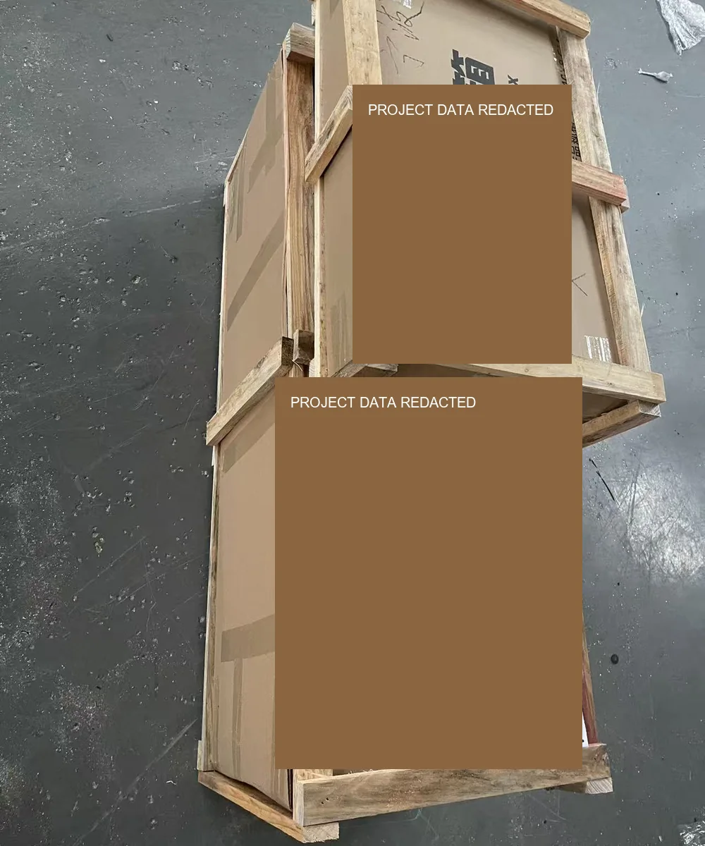
Crate where required
Project and shipping fields are solid-redacted. Final transport sections, protection and crate use are confirmed for the actual route.
Provide overall dimensions, visible seams or segmentation limits, access constraints and the largest transportable section.
Confirm service access, structural interface, power route, graphic face and the local conditions that affect the reviewed structure.
Send destination, indoor/outdoor context, mounting substrate, local installation responsibility, lifting/access constraints and target date.
02 / Configuration Architecture
Define six connected decisions before manufacturing
These are configuration variables, not fixed catalogue promises.
Finished geometry
Width, height, orientation, quantity, panel divisions and intended visual context. No universal maximum is stated.
Frame & sectioning
Profile direction, divisions, connection route and internal support against the drawing, transport route and site access.
Fabric interface
Graphic format, tensioning or silicone-edge requirement, graphic-change expectation and finishing responsibility.
Lighting layout
Rear depth, geometry, illumination intent, voltage market, wiring access and service requirement.
Mounting & service
Wall, facade or another interface plus access and local responsibility. Loads and anchors remain separate inputs.
Supply & packing state
Required supplied condition, shipping constraints, included components, protection and handoff.
03 / Manufacturing Evidence
One physical project sequence, three different decisions
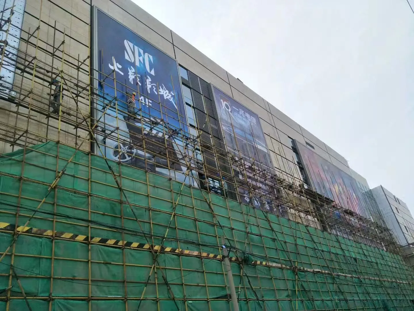
The approved Shanghai sequence shows facade context, rear lighting and a physical tensioning/profile detail. It is evidence from one project—not a maximum-size specification, engineering standard or universal installation promise.
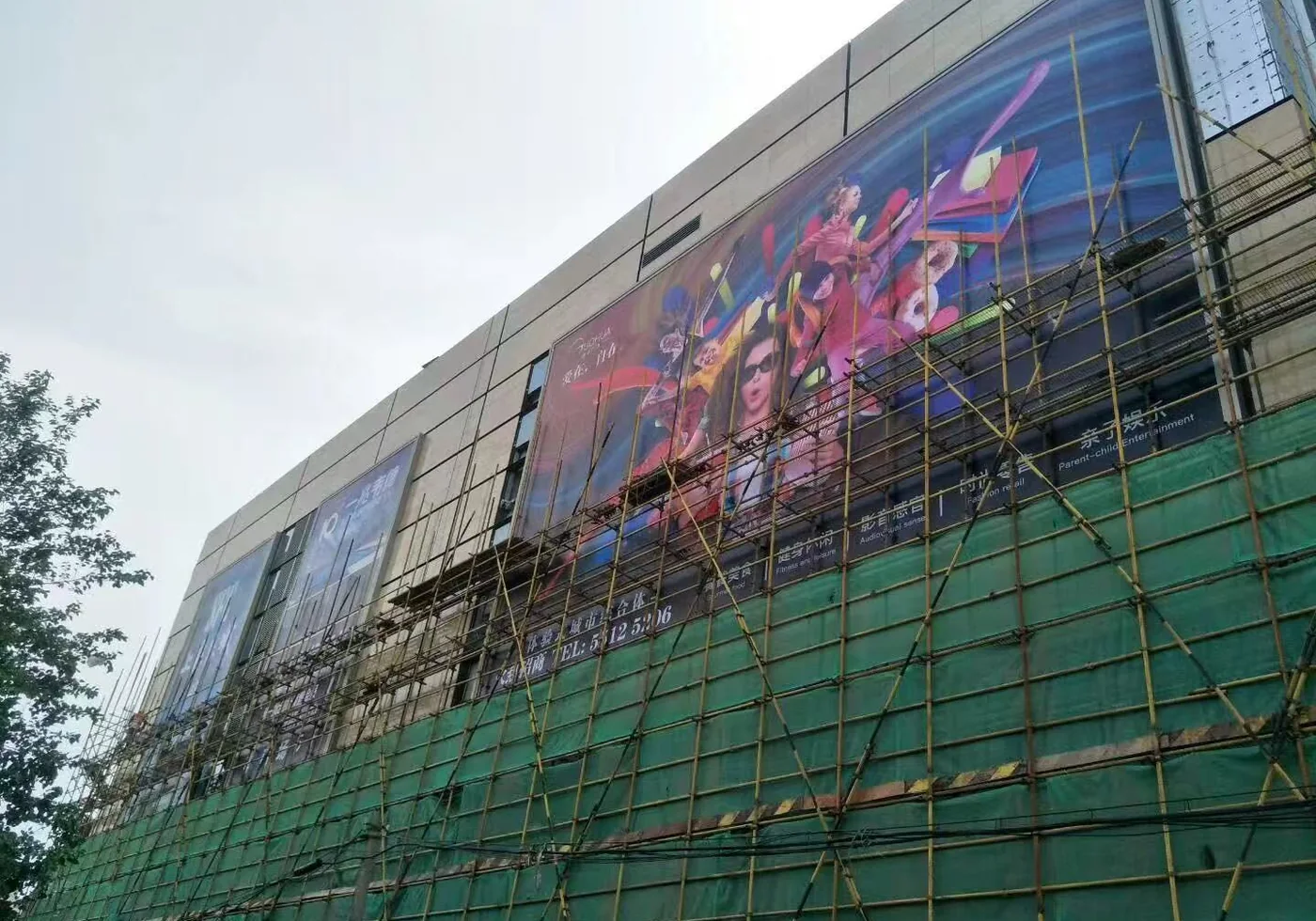
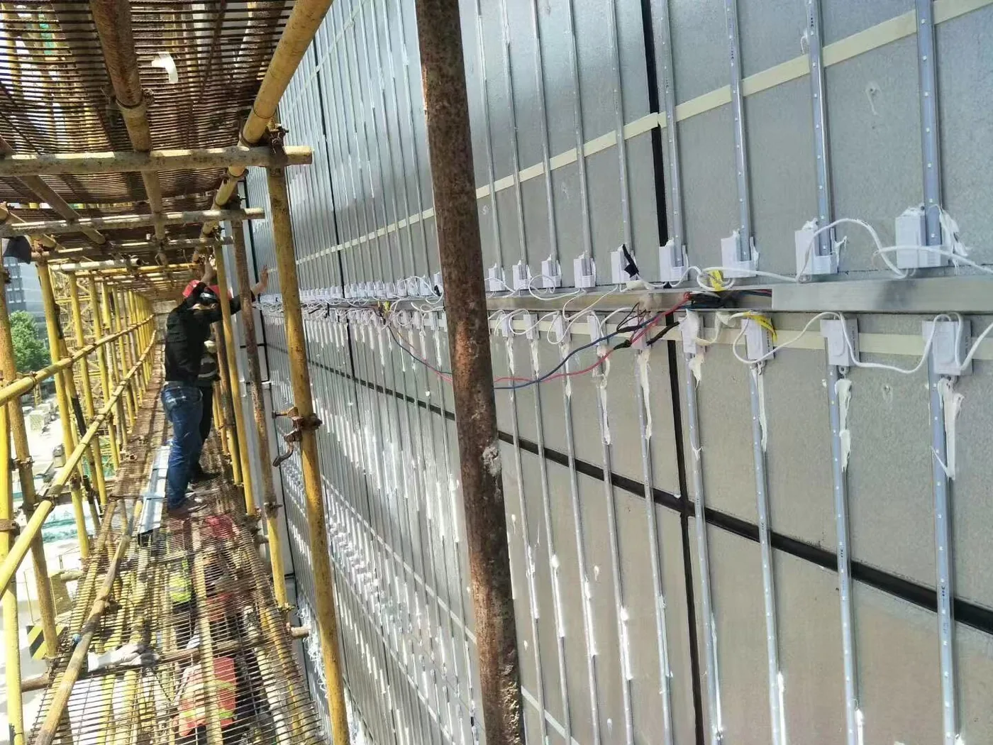
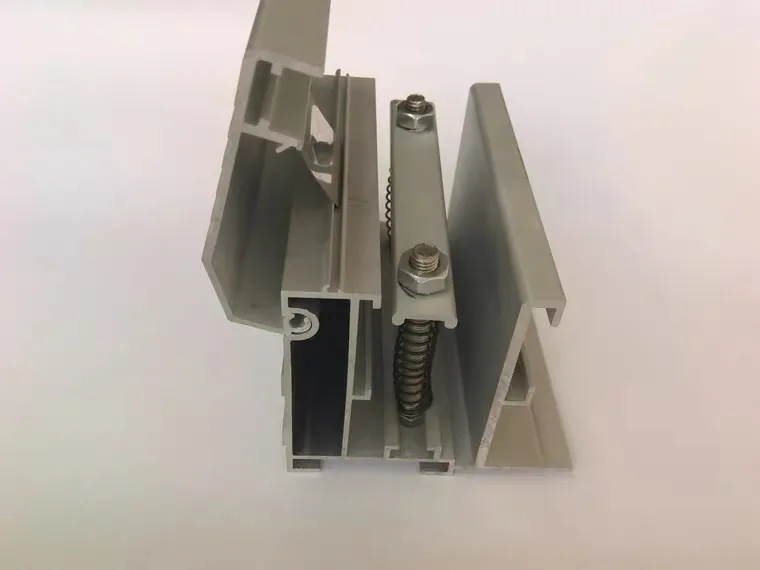
The project record does not establish a published area limit, full facade-engineering scope or turnkey installation responsibility. View the Shanghai evidence case →
04–05 / Buyers & Decision Matrix
For trade buyers managing scale, graphics and site constraints
Drawing-led frame, lighting and supplied-condition decisions for active signage projects.
Graphic dimensions, fabric finishing, frame divisions and transport or installation handling.
Retail, exhibition or commercial displays requiring a defined frame, lighting and site interface.
Displays that must connect with a wall, fixture, access route or project-specific interior condition.
Buyer Provides
Finished geometry, graphics, site and mounting context, lighting intent, quantity, destination, target date and desired supplied condition.
Ningora Confirms
Manufacturable configuration, frame divisions, component and wiring direction, included interfaces, packing, MOQ and lead time.
06 / Factory-Direct Project Manufacturing
From confirmed drawing to protected supply
Ningora manufactures the agreed frame and light box scope around the confirmed project requirement. Included components and responsibilities are stated before quotation.
Drawing & configuration
Geometry, frame divisions, graphic condition, lighting, interfaces and supplied condition are aligned.
Profile processing
Frame sections and project-specific structural elements are prepared to the confirmed drawing and quoted scope.
Assembly & integration
Connections, internal elements and agreed lighting or wiring components are assembled.
Project-specific checks
Applicable dimensional, wiring, power-on, light-on or function checks are defined per project.
Protective packing
Protection and packing are confirmed against section lengths, components, destination and supply state.
This is not a claim of formal universal QC, burn-in testing or a standardized export-packing system.
07 / Project Path
Move from a facade or display brief to a confirmed manufacturing scope
Project Brief
Application, geometry, quantity, site context, destination and target date.
Drawing Review
Frame divisions, interfaces, lighting space, access and supplied condition.
Manufacturing Scope
Frame, components, assembly, checks and any sample or approval stage.
Quotation & Packing
Included items, protection, MOQ, lead time and commercial conditions.
08 / What the Buyer Should Send
Prepare the drawing, site and supply inputs together
Start with the information available. Only send drawings and references you are authorized to share.
- Application, site type and viewing context
- Finished width × height, orientation, unit and quantity
- Single- or double-sided requirement
- Mounting, substrate, access and local responsibility
- Graphic format and fabric-finishing responsibility
- Lighting intent, rear depth, voltage market and service access
- Transport or maximum section-length constraints
- Desired supplied condition, destination and target date
09 / FAQ
Before you submit a large-format requirement
10 / RFQ CTA
Prepare a Large-Format SEG Manufacturing Brief
Send the finished geometry, quantity, site and mounting context, graphic requirement, lighting brief, section or access constraints, destination and target date. Ningora will identify the missing information before the manufacturing and commercial scope is confirmed.